What is Geometric Dimensioning and Tolerancing?
The need for quality within manufacturing is paramount and it is crucial that the design intent and functionality of a part be clearly communicated among the design, production, and inspection teams. However, manufactured parts always differ from the original CAD model due to variations in the manufacturing process. So how do manufacturers control the inherent part variations while still achieving the necessary level of quality? The answer is Geometric Dimensioning and Tolerancing (GD&T) – and the result is improved communication and quality!
Simply put, GD&T is a system for establishing and communicating engineering tolerances within manufacturing. It is a language of symbols and standards that communicate the design intent of the part and its permittable tolerance for variation. GD&T defines part dimensions as well as the location, size, shape, and orientation of any part features. The GD&T methodology takes into consideration the function of a part and how that part interacts with any related parts.
GD&T is used on engineering drawings and within computer-generated models to communicate to the manufacturing team and equipment what level of accuracy and precision is required for a given part. The GD&T system has established rules and standards used throughout the world. The standard used by companies within the United States, and by many other companies worldwide, is ASME Y14.5 as defined by the American Society of Mechanical Engineers (ASME). The GD&T methodology is currently employed across many industries including medical, defense, consumer goods, aviation, automotive, heavy machinery, and others.
A Deeper Dive into GD&T Methodology
Within GD&T, “geometric” refers to various forms, such as a plane, cylinder, or square. From a theoretical perspective, these forms are perfect, but since it is not feasible to manufacture perfect parts, the amount of tolerable variation from the perfect form must be specified. Engineering drawings use GD&T language to specify the minimum and maximum acceptable variations, or tolerances. Below are examples of the geometric characteristics and corresponding symbols as well as the nomenclature commonly used with GD&T.
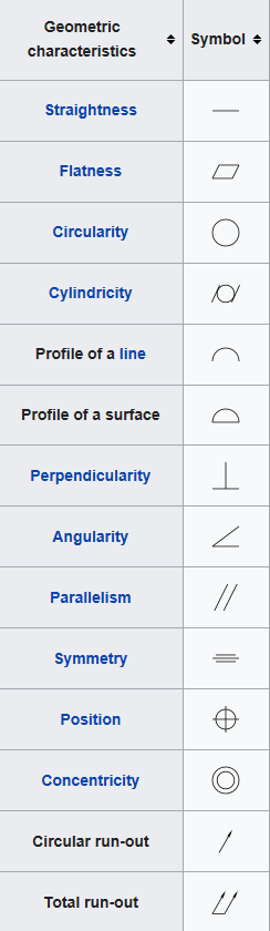
Credit: Wikipedia
- Datum Reference Frame (DRF): this is a 3D Cartesian coordinate system used in engineering drawings. DRF is the frame of reference and origin of all dimensions and geometric specifications on a given drawing.
- Datums: these are the points, lines, and planes that make up the DRF in drawings and are the exact anchors to which the part dimensions and tolerances are referenced. It is important to keep in mind that datums are theoretical, and therefore, perfect. For example, a datum could be a straight line on the drawing denoting a part’s flat surface.
- Datum Features: these are the features of the part such as holes. Datum features are real and tangible, and therefore, have variation. For example, a datum feature would be the part’s actual surface which is never truly flat due to small bumps from variations that occur during manufacturing, and therefore, is shown on the drawing as a straight line with a given tolerance to describe the level of variation permitted in the part’s surface straightness.
The Benefits of GD&T
As innovation and technology continue to advance within plastic injection molding, part tolerances are becoming tighter and tighter; however, tightening tolerances unnecessarily can significantly increase costs due to higher tooling expenses and quality issues. Additionally, if tight tolerances are not achieved properly the resulting products may underperform or even fail - this is why GD&T is so crucial!
GD&T offers the ability to improve quality, decrease cost, and increase speed to market. The GD&T drawing is the continuous thread that connects the design and manufacturing teams and keeps everyone speaking the same language – literally! By engaging the production team during the design, the part functionality can be discussed upfront and the team can jointly develop a manufacturing process that will produce high-precision components - avoiding overly tight tolerances that often drive up cost and result in quality issues during manufacturing. For these reasons, it is crucial for OEMs to partner with an injection molder, such as Crescent Industries, who has Design for Manufacturability (DFM) expertise; this simply means the design and manufacturing teams are integrated to allow manufacturability issues to be identified and addressed during the design process – saving significant time and cost!
Below are more details on the key benefits that GD&T offers: improved communication, increased flexibility, and enhanced quality – all 3 of which result in cost savings and improved speed to market!
- Enhanced Communication: the vital role of communication in the manufacturing process cannot be overstated. Today’s complex part designs require accurate communication across the various disciplines. The use of a single and standardized GD&T language ensures engineering, design, production, and quality teams are able to communicate clearly and accurately with each other, saving time and increasing efficiency.
- Improved Reliability and Quality: with all teams using a consistent language, GD&T avoids the misinterpretations that often occur with crowded and confusing drawing notes and instead allows for the desired dimensional and functional specifications to be achieved. Part production becomes more repeatable and consistent – simplifying inspection, reducing the part rejection rate, and improving quality.
- Increased Flexibility: as a general rule of thumb, designers should keep tolerances as large as possible while maintaining the desired functionality of the part. Manufacturers may think using GD&T results in tighter tolerances; however, GD&T actually results in more manufacturing flexibility and larger tolerances, especially for intricate or complex designs! GD&T specifies the design intent instead of the specific geometry, providing the appropriate tolerances that maximize production. For example, when GD&T data communicates functional requirements such as how the position of a hole can vary while still allowing for proper assembly, the greatest tolerance range can be utilized without impacting part function – resulting in lower design and manufacturing costs and improving quality while achieving the original design intent!
Crescent Injection Molding Capabilities
For over 75 years, Crescent has been providing an integrated single source solution for customer’s plastic injection molded components utilizing our advanced engineering capabilities, in-houses tooling, and production facilities. Our capabilities allow us to mold a comprehensive range of engineered and commodity grade resins. We currently serve the medical, pharmaceutical, dental, defense, safety, electrical/electronic, aerospace and OEM/Industrial markets.
Contact us today to learn more about our complete manufacturing solutions.
