
 (Updated May 2019)
Two aspects of injection mold design that have great impact on part quality are cooling and venting. If the injection mold has poor cooling, the result could be increased cycle times, scrap and dimensional problems while inadequate heat could result in short shots and poor surface finishes. Venting allows for displaced air in the cavity to escape. If there is inadequate venting, gas burns or non-filled parts can result. If there is too much venting, excessive flash will be the result.
Optimizing Cooling
The cooling process is the most time-consuming step in plastic injection molding and takes up over 75% of most cycle times – so it is important to get the cooling design and process conditions right! The biggest problem with the cooling process for plastic injection molding is that a poorly cooled part increases issues that are difficult to resolve. Some of these issues include an increase in cycle times, an increase in scrap, as well as additional problems with part dimensions.
This is why optimization of the cooling processes is so important. Cooling includes a lot of variables such as:
- The thermal properties of the plastic being molded and the materials used in mold construction
- Energy balance from melt preparation to cooling cycle time
- The influence of coolant flow rate on heat transfer efficiency
- Mold temperature controller selection
- Quality design practices for optimum mold cooling
Every plastic part produced requires a very specific amount of energy to plasticate solid resin pellets. This means that an identical amount of heat energy needs to be removed before it will form a stable part. It is important to remember that energy out - needs to equal energy in.
In every mold, there is also a huge amount of variation in the rate at which heat travels through the steel. Copper and aluminum are excellent heat transfer materials. However, they are soft metals and are not used for large-scale production runs.
Coolant flow rates are the most critical aspects of mold cooling. Having a turbulent flow of the coolant is also important and gives good heat transfer from the steel to the coolant. Increasing the velocity and turbulence of the coolant also improves temperature differences throughout the mold.
Mold cooling is also affected by the specific resin being used, since different resins have different heat transfer rates. Some materials require more cooling in the mold than others to achieve the same results. This same dynamic exists for the materials used in mold construction.
Cooling lines in the mold need to be designed specific to the part being molded. Thick areas of the part will take longer to cool and should have more aggressive cooling than thin areas. Cooling lines should also be as direct as possible, with minimal branches and divisions. This will reduce pressure drop in the cooling system.
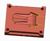
Traditional cooling methods are similar to a heat exchanger, often with long, tubes, typically straight or U-shaped, running through the mold to facilitate the cooling step. An alternative approach is conformal cooling where the cooling channels closely follow the shape of the component being produced. Conformal cooling tubes follow the bends and turns of complex part designs, and are not limited to the straight channels that are typically created by traditional drilling or milling. Conformal cooling typically has higher initial tooling costs but provides better cooling efficiency and lower cycle times.
Essential Venting Requirements
A properly designed and built mold is nearly air tight. This is required so that flash does not occur, which is unwanted plastic beyond the boundaries of the part. But without venting, the mold would not fill properly, because the air that’s in the mold cavity has nowhere to go while the plastic is entering. The pressurized air produces heat, and if too excessive can produce burn marks on the molded part. Gasses given off by the molten plastic also increase the air pressure in the mold cavity, further complicating the problem.
A part in this molding condition is also unlikely to fill completely, since the pressurized air is restricting the flow of the plastic resin. The result is “short shot”, a part which is incomplete. To resolve this issue, vents are machined into the mold tooling. A properly designed vent is deep enough to allow the trapped air and gasses to escape but not deep enough to allow the plastic to flash. There are a few different ways in which mold tooling can be vented.
Standard Venting
In a standard vent, a small channel is machined at the parting line. The "primary" area of this vent is very thin, allowing only the air to escape, and is usually very short, usually .030 to .050, depending on the material being used. The "secondary" area of the vent is a deeper channel that connects the "primary" vent to the outside atmosphere.
Ejector Pin Venting
Ejector pins themselves provide natural venting; since the clearance required for an ejector pin to operate is often enough to effectively vent a plastic part. In areas where more aggressive venting is required, primary and secondary vents can be added to the ejector pin.
Peripheral Venting
In this venting scenario, the primary vent continues around the part or all of the parts periphery. This is used when maximum venting is required at the parting line.
Runner Venting
If the runner is not properly vented - all of the air that was originally in the runner system will be added to the mold cavity as it fills with plastic. When a large runner is used, this can create more trapped air, especially when the runner is significantly bigger than the size of the part. Runners are usually vented with a standard vent as close to the gate as possible.
Venting has a big impact on part quality so the number of vents and locations need to be designed correctly. Below are best practices for optimizing venting.
- Allow as many escape routes as possible for the enclosed air to vent from the mold.
- Vents should run from the edge of the mold to the mold exterior.
- When sizing the depth of the vents, they should be sufficiently deep to let air escape but not so deep that plastic can seep out.
- When designing vents for the mold, ensure you consider all of the tooling such as runners, sprues, actions, or slides.
- Machined vents need regular cleaning and inspection to prevent clogging.
- If you are experiencing issues associated with poor venting such as short shots or warpage, consider increasing the size or number of vents, or perhaps a different vent location may resolve the issue. Additionally, if you are having issues with flash, the vent depth may be too deep.
For your next project, Crescent Industries offers 70+ years of injection mold tooling and molding expertise to help make your job easier.
For additional information, please click below to get our white paper “How to Overcome Common Design Concerns for Injection Molded Components”. This white paper addresses some of the key concerns in the design step that are a 'must' to consider.
Information for this article came from;
Go With the Flow: Mold Cooling Optimization From a Moldmaker's Perspective by GP Reny was published by Mold Making Technology.
Injection-mold Venting: the hidden processing parameter written by Paul Allen